Download the firmware you are wanting to improve. Steve Goossens has a really nice patching guide that has links to the Nikon download archives, if you are looking for older firmware.
Open the firmware in the Nikon-Patch Local UI tool (It is a C# project, so you will need a windows pc and Visual Studio 2019 Community to run it) and decode/exact the firmware
The main UI firmware is the B firmware, we will open that in Ghidra
So demonstrating with the D3300 1.02 firmware, we get the files a860_010101.bin and b860_102.bin from the decode step.
So create a new Ghidra project, then import the B firmware
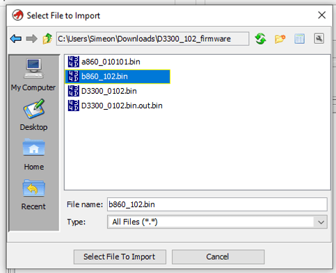
Then select the ARM v7 little endian
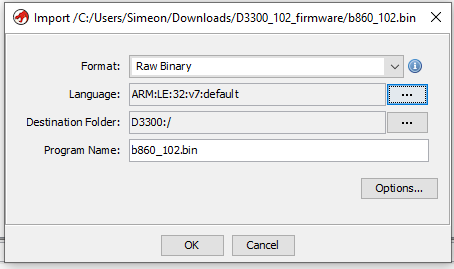
Finding the firmware offset
For now ignore the Options, but we will come back and load the file at the correct offset later. Also for the next couple of step don’t save anything, as we will be deleting and re-importing files as we work out, where the files should be loaded.
Once we open the file, you will be prompted to “Auto disassemble this file” say No you that, and press d key on the first line
this will look like:
    //
    // ram
    // ram:00000000-ram:016bff89
    //
         assume spsr = 0x0  (Default)
                         Reset                                           XREF[1]:     Entry Point(*)
    00000000 18 f0 9f e5     ldr        pc=>LAB_90352fe0,[DAT_00000020]                  = 90352FE0h
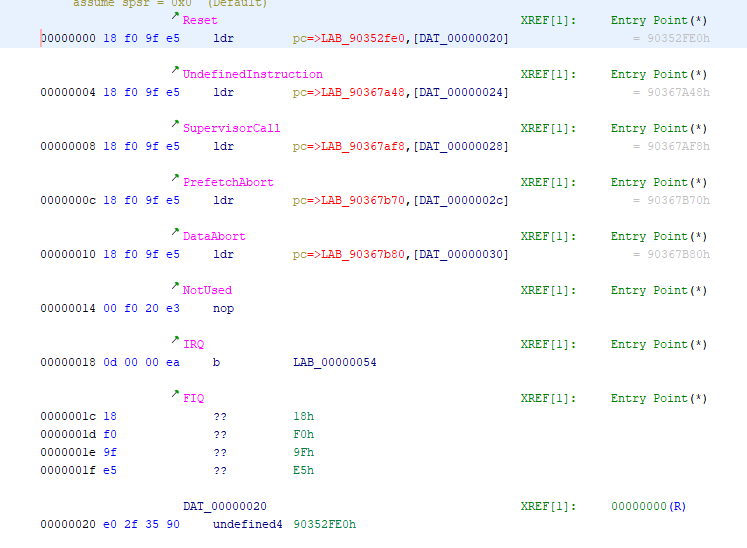
This is noting the B firware reset jump address is loaded from 0x20 in the firmware, which is address 0x90352FE0, and Nikon B firmwares follow a pattern of being at 0xNN020000 thus this model camera is loaded at 0x90020000
Now we have the correct offset, close the CodeBrowser and don’t save
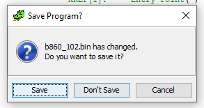
Deleted the firmware from the project, and confirm yes to permanently deleting
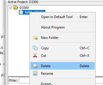
and reimport, but this time set the memory offset
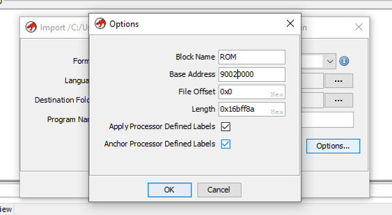
Now we open the CodeBrower again, and again say no to the Analyze option. Because this time we are wanting to learn the address the itron kernel gets loaded to, and if we have that memory mapped before the auto magic process begins, there is a lot of errors avoided.

So here we are going to decode the first jump, and follow that twice, and then we will be in the reset function (at 0x90352fe8 hit f to mark that as a function) and then scroll there are some sections where a repeating pattern occurs, that is a serries of MemCopy operations.
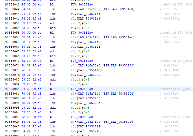
clicking on the addres 9035329f we see some code that looks like this. It’s loading 48 bytes into all the spare registers via the LDMIA instruction and then writing them to the destination. This is the memcopy we are looking for.
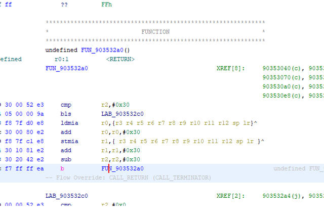
So now we can right click on the function in the Disassembler window and Edit Function Signature
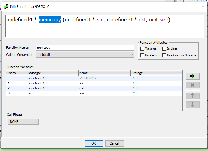
and then the jumping back to the reset (Alt+LeftArrow steps back) function will look like:
FUN_903533a0(PTR_DAT_903531cc,PTR_DAT_903531d0,0xae000000);
FUN_90020098();
memcopy((undefined4 *)PTR_LAB_903531d4,DAT_903531d8,DAT_903531dc + 3U & 0xfffffffc);
memcopy((undefined4 *)PTR_LAB_903531e0,DAT_903531e4,DAT_903531e8 + 3U & 0xfffffffc);
memcopy((undefined4 *)PTR_LAB_903531ec,DAT_903531f0,DAT_903531f4 + 3U & 0xfffffffc);
memcopy((undefined4 *)PTR_DAT_903531f8,DAT_903531fc,DAT_90353200 + 3U & 0xfffffffc);
memcopy((undefined4 *)PTR_DAT_90353204,DAT_90353208,DAT_9035320c + 3U & 0xfffffffc);
memcopy((undefined4 *)PTR_DAT_90353210,DAT_90353214,DAT_90353218 + 3U & 0xfffffffc);
FUN_900200a4();
dst = (undefined4 *)((DAT_9035321c & 0xfff00000) + 0x100000);
which looks strange, because the destination pointers are not followed. But we can alter the memory mapping to drop Write from the ROM area
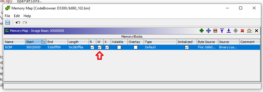
and the code then becomes:
memcopy((undefined4 *)&LAB_9158a358,(undefined4 *)0x10000000,0x3b5b4);
memcopy((undefined4 *)&LAB_915c590c,(undefined4 *)0x1003b5b4,0x179c);
memcopy((undefined4 *)&LAB_915c590c,(undefined4 *)0x1003b5b4,0);
memcopy((undefined4 *)&DAT_916a73a0,(undefined4 *)0x1011d420,0x28b3c);
memcopy((undefined4 *)&DAT_916a73a0,(undefined4 *)0x1011d420,0);
memcopy((undefined4 *)&DAT_916a739c,(undefined4 *)0x1011d03c,4);
Now we know the offsets we need to add as memory maps, on the very screen we used to fix the ROM value, the “Memory Map” screen. Really only those three blocks are needed to be mapped, these are RAM area’s and there is some general RAM that needs to be identified, but for now this is the start we need.
Which is exactly what I have been noting in the Firmware Notes in the code repo, when I remember.
So now we can delete all this again, and load the code base firmware at the correct location, and add the memory maps, and then press Auto Analyze and walk away for a cup of tea.
Adding the Kernel memory maps
So using the find or Firmware Notes values we want to add the three blocks of memory for the Code, Data, and ? third data segments:
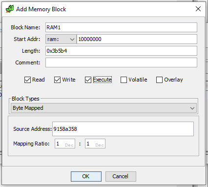
repeat for RAM2 and RAM3
and you will end up with
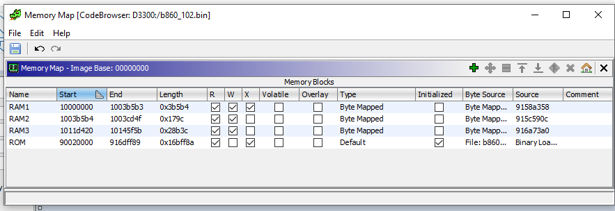
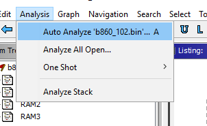
Now it’s time to Auto Analyze
Going forward from here
There are number of landmarks to look out for, there is a chunk of kernel debugging, that you can find the strings for, and then find the stubbed print finctions, thus find all calls, those give a lot of details, there is a small amount of RTTI information, there are some documented protocols like the TIFF/JPG header writing code, the PTP handlers are driven by tables, so are quite easy to find, the EyeFi code can be found quickly.
And then there is the method of loading other camera models firmware, side-by-side, and looking for the addresses of existing patches and finding the related code.
I intend to write more on most of these things, but it also has taken me 4+ years to write this up, so it’s not going to happen overnight…
